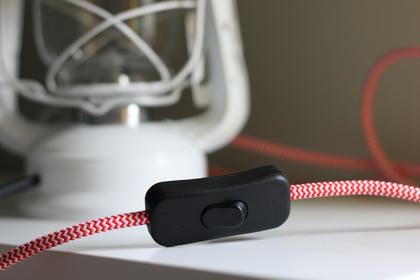
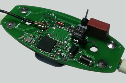
Smart, Bluetooth-controlled cord light switch
This article describes my attempt to design a remote controlled switch for corded lamps (such as desktop lamps or wall fixtures).
This idea is certainly not new, and there are plenty of ready-to-use modules on the market that can help you ‘augment’ any given lamp with such ability. There is one issue though - most small lamps have a switch already, and quite often it is located on the cord. Such switches work by cutting the power from the lamp body, turning the bulb on and off.
That makes it impossible to locate an electronic module in the lamp itself - it will simply be powered off once the user flips the switch. I’ve seen a lamp that works that way - and I personally do not like such approach at all.
Instead, I propose a combined device that looks and feels like a regular cord switch, but has embedded hardware inside. Such switch multiplexes user actions with remote control instructions, providing very natural and smooth user experience.
The idea
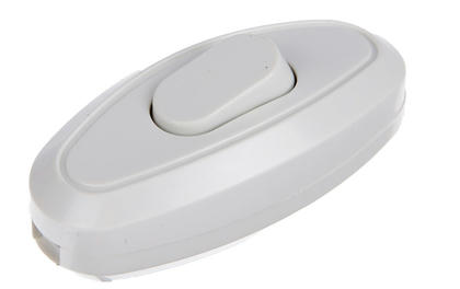
As a base for the design I took an in-line cord switch from the local appliance store. It was necessary to remove all of the components and plastic bits from the inside, leaving just an empty shell.
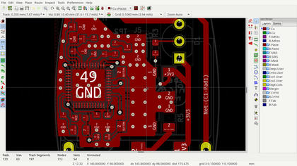
Then I measured the case and sketched out the future board outline in Corel Draw. After a couple of iterations with paper and scissors I finally got the sketch that fitted the case well, which was then exported to Kicad.
Schematics
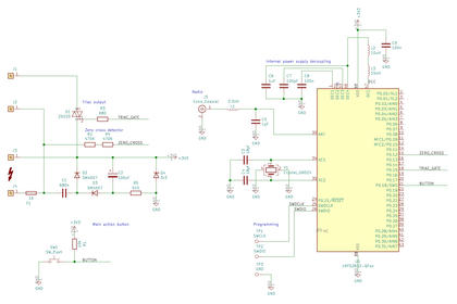
The main part of the board is NRF52832 from Nordic Semi - a Cortex-M4 based microcontroller combined with a Bluetooth-capable radio in a single QFN48 package. I like this chip a lot, and I use it extensively in almost all of my recent designs. The chip is wired according to the reference manual.
The most outstanding part here is the power supply. The space inside the switch is probably too limited to fit a proper switcher or a transformer. No worries though - considering how low is the current consumption of the board, it’s not actually required.
Instead, this board uses a capacitive power supply, also known as a capacitive dropper. It’s very similar to resistive divider - the only difference is that it uses capacitive reactance instead of the resistors. Wikipedia has a nice overview on that design if you’d like to know more.
It’s important to take extra care choosing space between power supply components to eliminate the possibility of arcing. Other than that the routing was pretty straightforward.
Assembly
Such QFNs are a bit tricky to solder because of the central pad - it dissipates a lot of heat, and if your soldering station is not powerful enough the chip can easily ‘glue’ to the board. I recommend placing a small drop of solder on the pad first - it helps the chip to “flow”, making some adjustments possible.
First revision contains a mistake - there is no resistor that discharges power supply capacitor when the device is unplugged. So I did a quick hack and soldered a TH resistor on top of the capacitor (it’s something like 300k in my case). I recommend you to do so as well if you’re assembling this outdated revision.
Firmware
As any other Cortex-M microcontroller NRF52 is programmed using the SWD interface. The device unfortunately lacks the programming connector - typical 2.54 pin header is too large for this small board. SWD is exposed on the pads, and you have to solder some wires there. I use the cheap STLink clone from AliExpress to flash the firmware.
There is no ready-to-use firmware developed as of now.
One more thing to consider while developing code for this board is the usage of low-frequency (LF) clock. The most power-saving (and thus, recommended) source for this clock is an external crystal attached to the microcontroller, however this board lacks it because of the space requirements.
So if you plan to use any of the NRF52 examples you have to explicitly set the source of the LF clock to internal (RC) in your config.h file.
Take a look at my cool NRF52 template - I use it for all of my recent NRF52 projects.
Software
Bluetooth low energy is widely supported both by mobile and desktop platforms. Considering that there is no firmware yet, it’s hard to give any concrete directions. If you’re a Linux user (such as I am), you can try using BluePy library:
from bluepy import btle as ble

mac = ...
service_uuid = ...
char_uuid = ...

device = ble.Peripheral()
try:
    device.connect(mac)

    service = device.getServiceByUUID(service_uuid)
    chars = service.getCharacteristics(char_uuid)

    if chars:
        chars[0].write(...)

except ble.BTLEException:
    raise
finally:
    device.disconnect()
Another solution would be to use MQTT to BLE bridge, making the device available to the members of a local network. In that case it would be possible to use ready-to-use home automation tools such as Home Assistant, or easily develop custom applications in any language you’d like:
struct mosquitto *handle;

mosquitto_lib_init();
handle = mosquitto_new(NULL, true, 0);

if (!handle) {
	...
}

mosquitto_connect_callback_set(handle, connect_callback);
mosquitto_message_callback_set(handle, message_callback);

... = mosquitto_connect(handle, mqtt_host, mqtt_port, 60);
/* error handling omitted... */

mosquitto_subscribe(handle, NULL, "/mqtt/topic/", 0);

for (;;) {
	... = mosquitto_loop(handle, -1, 1);
	/* handle exit or reconnect in case of an error ... */
}

mosquitto_destroy(handle);
mosquitto_lib_cleanup();
Links
My GitHub repo with the sources for the board
There is a newer revision being developed - take a look at the branches there.
